Home > User Interface > Results Processing > Structural Code Check Post-Processing > Code check concrete
Concrete Code Check Parameters
1. Concrete parameters
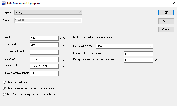
*Figure 1 : Steel material properties panel in DeepLines Wind *
A. Class of the cement
Has influence on:
-
Mean compression strength
-
Desiccation withdrawal
EN 1992 1-1 classifies in 3 different classes : R, N and S. Those classes define the coefficient s, used to calculate βcc(t) in equation 3.2 of EN 1992 1-1:
It allows to calculate fcm(t) in equation 3.1 (EN 1992 1-1):
Where:
-
\(f_{cm}(t)\) is the average compressive strength of concrete at \(t\) days
-
\(f_{cm}\) is the average compressive strength of concrete at 28 days
\(f_{cm}(t)\) being proportional to \(\beta_{CC}(t)\), the graph below allows us to see the influence of the cement class on the concrete’s compressive strength.
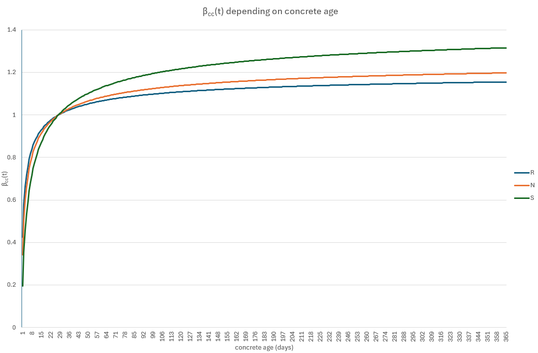
Figure 2 : \(\beta_{CC}(t)\) depending on concrete age
Thus, the cement class will have influence on the concrete compressive strength not only after, but also before the 28 days needed to reach most of its compressive strength (80 to 95%)
The class of cement will also be used to determine the coefficient αds1 and αds2, which will then be used to calculate the relative strain due to desiccation withdrawal \(\epsilon_{cd,0}\) in equation B.11 of EN 1992 1-1 :
Where:
-
\(f_{cm}\) is the average compression strength in MPa
-
\(f_{cm0}\) = 10 MPa
-
\(\beta_{RH}\) is a coefficient depending on the relative humidity and define by expression B.12
The graph below allows us to determine which class of cement would lead to a higher desiccation strain.
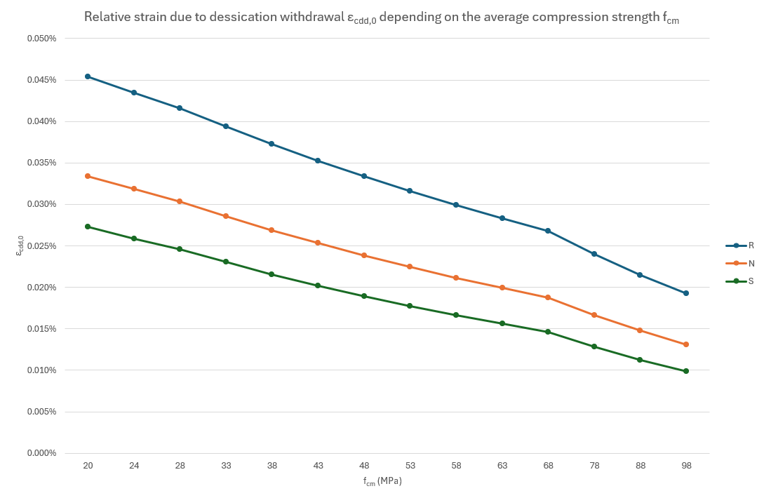
Figure 3 : \(\epsilon_{cd,0}\) vs \(f_{cm}\)
Therefore, in the case of floating offshore wind turbines, concrete should be aged of at least 28 days when commissioned. When the cement class used is unknown, it’s possible to consider a class R cement to stay conservative
B. Type of the concrete
Lightweight or standard, this parameter has an influence on the density and all the mechanical properties of the concrete (modifies the equations). Lightweight concrete is generally used for coating and structures where mass is considered.
Lightweight concrete’s density goes from 800 kg/m3 to 2200 kg/m3 while standard concrete’s density is set between 2200 and 2400kg/m3.
C. Stress-strain diagram
Stress-strain diagram is used to determine which way the concrete compression strain \(\epsilon C\) is calculated, which is taken into account calculating the compression stress \(\sigma C\). The parabola-rectangle diagram is the one used by default but the bilinear diagram (which is a simplification) can also be used with the condition that equations are equivalents or more conservative.
D. Partial factors
Partial factors linked to materials are defined in table 2.1N of the EN 1992 1-1:
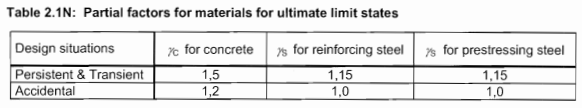
Figure 4 : Partial factors linked to materials (EN 1992 1-1)
Partial factor for the elastic modulus \(\gamma_{c e}\) is set to 1.2 by the EN 1992 1-1 (5.8.6(3)).
E. Characteristic compressive cylinder strength of concrete at 28 days
This property is defined by the resistance class of the concrete (which is noted CX/Y, X being the characteristic compression strength at 28 days on a cylinder and Y being the characteristic compression strength at 28 days on a cube). Each resistance class à specific values for each mechanical properties (resistances, elastic modulus, strain limit, etc.). Those values are not the same for lightweight concrete.
Properties of each resistance class are summarized in tables 3.1 (standard concrete) and 11.3.1 (lightweight concrete) of EN 1992 1-1.
Reinforcing steel properties
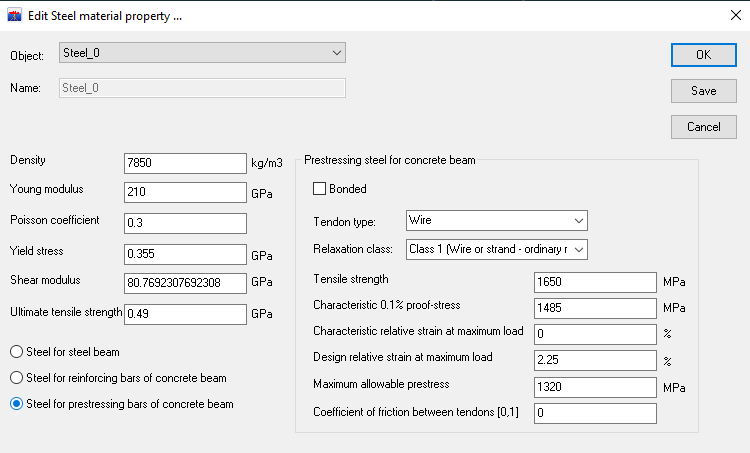
*Figure 5 : Steel material properties panel in DeepLines WIND *
A. Reinforcing class
Define the slope \(k\) of the steel ductility and the characteristic value of the relative strain \(\epsilon_{uk}\) at maximum load. Those classes are defined in table C.1 of EN 1992 1-1.
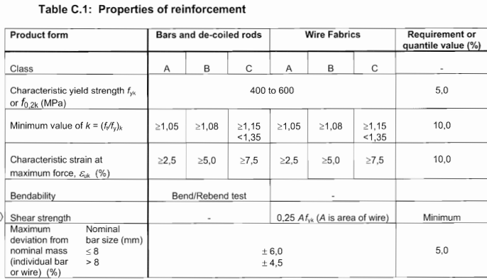
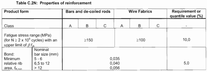
For fatigues studies, it is advised to use fatigues stress range and relative rib area given by table C.2N
B. Design relative strain at maximum load
Could be automatically modified when reinforcing class is chosen.
Prestressing steel properties
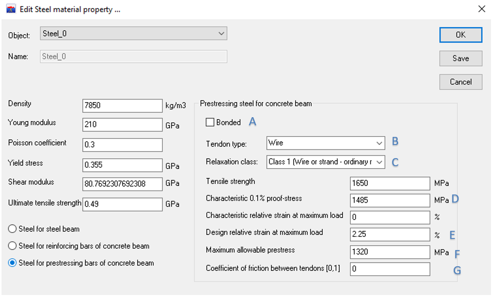
Figure 6 : Steel material properties panel in DeepLines WIND
A. Bonded
It’s unbonded when the ducts of the prestressing tendons are external or are not injected. It’s generally bonded.
B. Tendon type
There is 3 types of tendons described in the EN 1990 1-1: strands, wires and bars. Chosen one or another depends on the designing choices, but strands seem to be chosen more often in the construction industry.
C. Relaxation class
It mainly depends on the tendon type. Unsing bars, it will inevitably be a class 3. If prestressing tendons are wires or strands, it will be necessary to chose between class 1 or 2, the first one having the highest relaxation.
D. Characteristic 0.1% proof-stress (\(f_{p0.1k}\))
Directly depends on the tensile strength (\(f_{p0.1k}=0.9f_{pk}\)) in EN 1992 1-1 (7)), so it can be automatically computed when \(f_{pk}\) has been input.
E. Design relative strain at maximum load εud
Directly depend on the characteristic relative strain at maximum load (εud=0.9*εuk in EN 1992 1-1 (7)), so it can be automatically computed when εuk has been input.
F. Maximum allowable prestress
Depends on the minimum value between entre k1.fpk and k2.fp0.1k, k1 and k2 being given by the EN 1992 1-1 (Eq. 5.41), so it can be automatically computed.
G. Coefficient of friction between tendons
Defined by table 5.1 of EN 1992 1-1:
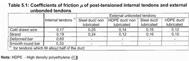
Could be automatically modified when the tendon type is chosen.
Code Check Options for EN 1992 1-1
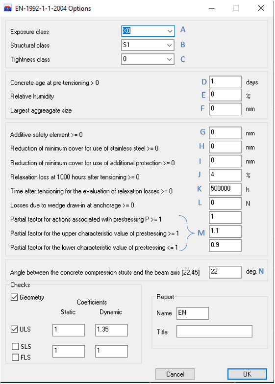
Figure 8 : Code check EN-1992-1-1-2004 panel in DeepLines WIND
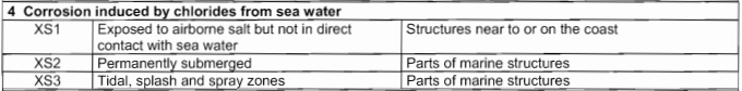
A. Exposure class
This parameter allows to consider the influence of environment. Considering an offshore floater, classes XS2 and XS3 seem to be the most appropriate (XS1 being mostly used for structures located on the ground near the shores). Table 4.1 of EN 1992 1-1 summarises the correspondence of the existing classes. Here is an extract of it:
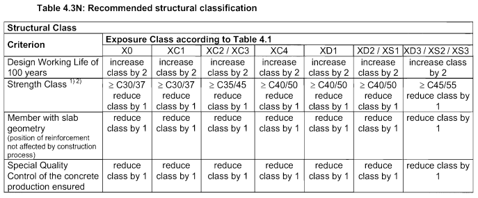
B. Structural class
Structural class will be taken into account when determining the minimum cover regarding the environment. The EN 1992 1-1 (4.4.1.2 (5)) recommends S4 as a default value. Table 4.3N indicates when the structural class has to be increased or decreased.
C. Tightness class
Defines leakage requirements. Tightness classes are defined in tab 7.105 of EN 1992-3
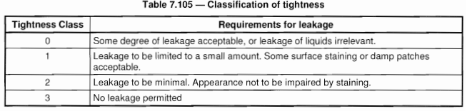
The pontoons of offshore floaters being also used as ballasts, a tightness class of 3 is required.
D. Concrete age at prestressing
This parameter will have an influence on creep and desiccation withdrawal. Its default value can be set at 28 days, duration needed by the concrete to reach its maximum strength after being cast. Age of concrete after being cast can also be considered.
E. Relative humidity
It’s the relative humidity of the environment when the concrete is cast and the curing of concrete. It will impact the desiccation withdrawal and the creep of concrete. The curing of concrete will avoid the water in concrete to evaporate before it hydrated all the cement’s grains and the concrete to reach the desired strength.
This information is provided by the entity that casted the concrete, but a value of at least 60% can be considered.
F. Largest aggregate size
Is taken into account to calculate the spacing between reinforcing bars, the spacing between the prestressed tendons and the minimum cover regarding the bounding. It’s an information provided by the entity that casted the concrete.
G. Additive safety element
It can be suited to increase the cover by this security margin. The value recommended by the EN 1992 1-1 (4.4.1.2 (6)) is 0mm.
H. Reduction of minimum cover for use of stainless steel
If reinforcing bars are made of stainless steel, it’s possible to reduce the cover. Base value recommended by the EN 1992 1-1 (4.4.1.2 (7)) is 0mm.
I. Reduction of minimum cover for use of additional protection
Coating can also be reduced if the concrete benefits from an additional protection (like coating). Recommended value by En 1992 1-1 (4.4.1.2 (8)) is 0mm.
J. Relaxation loss at 1000 hours after pre-stressing
This parameter directly depends on the relaxation class of the prestressing tendons. It could be automatically modified once the relaxation class is chosen. It could be wise to input this parameter directly in the material properties panel. Otherwise, if there are numerous tendons with different relaxation classes it couldn’t be taken into account.

K. Time after tensioning
For long time values, the EN 1992 1-1 (3.3.2 (8)) indicates that it’s possible to consider a duration of 500 000 (around 57 years)
L. Losses due to wedge draw-in at anchorage
Wedge draw-in at anchorage happens when the hydraulic cylinder releases the prestressing bar after tensioning it. The prestressing strength generated is transferred to the anchorage. It creates à displacement (from 1 to 12 mm) of the prestressing bar in the anchorage, which lead to a loss of the prestressing strength.
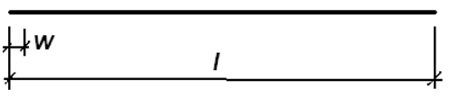
Figure 1 : prestressing steel bar with a length \(l\) and a wedge draw-in \(w\)
The sketch above represents a prestressing steel bar with a length \(l\) and a wedge draw-in \(w\).
The stress loss due to the wedge draw-in \(\Delta \sigma_{pw}\) is given by the following equation:
With \(E_p\), the elastic modulus of the prestressing steel.
If we consider \(S\), the section of the prestressing bar, and \(\Delta P_{sl}\), the prestressing strength loss, then:
\(E_p\), \(S\) and \(l\) being already filled out (or computed) in DeepLinesTM during the previous steps, the missing parameter is \(w\), whose default value should be 12mm when unknown, in order to be conservative.
M. Partial factor
For actions associated with prestressing
Fixed at 1.0 by EN 1992 1-1 (2.4.2.2)
For the upper characteristic value of prestressing
Fixed at 1.10 by EN 1992 1-1 (5.10.9)
For the lower characteristic value of prestressing
Fixed at 0.9 by EN 1992 1-1 (5.10.9)
N. Angle between the concrete compression struts and the beam axis
Compression struts represent areas where compression stresses transits in a beam under bending loads.
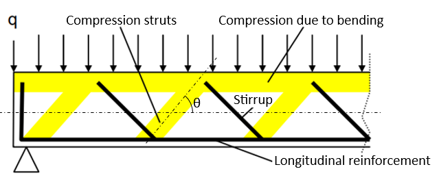
Their orientation is defined by angle θ. EN 1992 1-1 (6.2.3(2)) specifies its limits by \(cot \theta\):
Then, the value of \(\theta\) goes from 22° to 45°.
This value has influence on the shear loads sustained by the beam. The lower it will be, the higher the load sustained will be. It’s an information provided by the client.
Sources
The concrete society, Cement class in BS EN 1992 1-1 :
https://www.concrete.org.uk/fingertips-nuggets.asp?cmd=display&id=1058
Tout sur le béton, Le béton léger :
https://www.toutsurlebeton.fr/le-ba-ba-du-beton/le-beton-leger-avantage-utilisation-fabrication-prix/
Infociments, La précontrainte par post-tension dans les bâtiments :
https://www.infociments.fr/batiment/la-precontrainte-par-post-tension-dans-les-batiments
Ecole Polytechnique Fédérale de Laussane, Conception et dimensionnement de la précontrainte :
https://i-concrete.epfl.ch/cours/epfl/pb/2011/Support/ponts-1-P-2011-10-06.pdf
Infociment, Cure du béton :
https://www.infociments.fr/betons/cure-du-beton
Guide d’Agrément Technique Européen pour les procédés de précontrainte par post-tension (ETAG 013)
Flexion des poutres en béton précontraint (ENPC-BAEP2) :
https://pdfcoffee.com/enpc-baep2-2pertes-pdf-free.html
Prof. Ing. Jaroslav Procházka, CSc., Prestressed Concrete :
https://people.fsv.cvut.cz/~prochja2/Prestressed%20Con/Lecture%204.pdf
Dr. Ir. P. Boeraeve, Cours de Béton Armé Chap. 6 :
https://www.mcours.net/cours/pdf/hasclic1/hasclic851.pdf
