Home > User Interface > DeepLines model in Excel format
DeepLines model in Excel format
This section describes how a DeepLines model can be read or written in Excel format.
Model data in Excel format
Distribution of data in Excel sheets
The model data are to be provided in various Excel sheets. Each Excel sheet groups together data concerning the same type of data. The sheets names are fixed (see table below) and are sufficiently evocative enough to guess what type of object it is associated with.
Each entity defined in a sheet has a name and their data are defined mostly on one row in the sheet. Most of these names correspond to model object names like types or model components which appear in the tree model. Some of these names have no equivalent in the model, they are used to grouping data and to reference these data in other sheets.
The first column of the table below lists exhaustively the available sheets. For each sheet, the description of the data concerned by the sheet is shown in the second column. The third column gives the kind of object that will be defined:
- Type:
definition of a type whose name will appear in the Types folder or its sub-folders of the model tree. - Model component:
definition of a model component whose name will appear in the Model folder or its group sub-folders of the model tree. - Environment component:
definition of a component of an environment set. - Specific to Excel format:
definition of a set of data whose name can be referenced in another sheet and has not an equivalent in the model. These names are used to facilitate data entry in Excel format.
| Sheet name | Data description | Kind of defined object |
|---|---|---|
| DeepLines (or General) | Output file name in batch mode | Specific to Excel format |
| Flexible line type | Flexible line type data | (Line) Type |
| Generic line type | Generic line type data | (Line) Type |
| Rigid line type | Rigid line type data | (Line) Type |
| Cable-Chain line type | Cable/chain line type data | (Line) Type |
| Stiffener line type | Stiffener line type data | (Line) Type |
| Tapered line type | Tapered line type data | (Line) Type |
| DrillJoint line type | DrillJoint line type data | Type |
| Floater motion type | Floater motion type data | Type |
| Contact type | Data of the two types of contact type (line/line, line/surface) | Type |
| Buoyancy module type | Buoyancy module type data | Type |
| Fluid type | Data of the three types of fluid (Steady internal fluid, variable internal fluid, external fluid) | Type |
| Link properties | Data of the three types of link (String, Flexjoint, Load excursion) | Type |
| Marine growth | Marine growth data | Type |
| Foil profile | Drag/Lift aerodynamic data | Type |
| Drag lift | Drag/Lift hydrodynamic data | Type |
| Structure properties | Data of five types of Structure properties:
| Type |
| Table | Data of the two types of tables (Variation, Env) | Type |
| Mesh | Mesh description (only mesh with triangles and/or quadrangles) | Specific to Excel format. Used by objects: Floater, Rigid body, Sea&Ground |
| HAWT control mode | Wind turbine property: data of the control mode | Type |
| HAWT control Dll | Wind turbine property: data of the control Dll option | Type |
| HAWT aerodynamic | Wind turbine property: data of the aero solver option | Type |
| Fairlead | Fairlead data | Specific to Excel format. Used by objects: Floater, Buoy, Arch, Rigid body, Equipment, Sea&Ground |
| Connection | Data of the four types of connection between objects (Clamp, User-defined, Flexjoint, Spring) | Specific to Excel format. Used to connect lines with objects: Buoy, Ballast, Rigid body, Link |
| Line | Data of six kinds of line (Flexible line, Generic line, Drilling riser, Winch, Pipe with bends) | Model component |
| Section | Data of sections lines | Specific to Excel format. Used to define lines |
| Segment | Data lines sections segments | Model component / Line |
| Floater | Data of seven kinds of floater (FPSO, Semisub, CALM buoy, SPAR, Drill ship, Drill Semisub, Generic floater) | Model component |
| Substructure floater | Substructure floater data | Model component |
| Buoy | Buoy data | Model component |
| Arch | Arch data | Model component |
| Rigid body | Rigid body data | Model component |
| Equipment | Data of four kinds of equipment (LMRP, BOP, Wellhead, X-mas tree) | Model component |
| Ballast | Ballast property / Ballasted element | Type / Model component |
| Tensioner | Tensioner data | Model component |
| Telescopic joint | Telescopic joint data | Model component |
| Link | Data of the three kinds of link (Spring, Flexjoint, LoadExcursion) and their properties | Type / Model component |
| Pulley | Pulley data | Model component |
| HAWT | General data of a wind turbine | Model component |
| HAWT Blade | Data of wind turbine blades | Model component |
| HAWT Tower | Data of wind turbine tower | Model component |
| HAWT Nacelle | Data of wind turbine nacelle | Model component |
| HAWT Hub | Data of wind turbine hub | Model component |
| HAWT Shaft | Data of wind turbine shaft | Model component |
| Joint | Joint data | Model component |
| Sea&Ground | Sea & Ground data | Model component |
| Loading | Data of the 11 types of loading (Constant force, Incremental, Sinusoidal, Time dependant, Time dependant from file, Loading via dll, Concentrated Buoyancy modules, Inertia matrix, Damping matrix, Stiffness matrix, Lump masses) | Model component |
| Displacement | Data of the 8 types of displacement (Incremental, Sinusoidal, Uniform acceleration, Time dependant, Dis/Connection, LF motion, Control, Simplified turbine) | Model component |
| Rigidification | Rigidification data | Model component |
| Swell | Data of the Wave model component and of the three kinds of Swell environment (or wave) set component (Main swell, Secondary swell, Local sea) | Model or Environment component |
| Current | Current data | Model or Environment component |
| Wind | Wind data | Model or Environment component |
| Group | Group definition | Model component |
| Offset | Floater Motion Offset data | Environment component |
| LF motion | Floater Low frequency imposed Motion data | Environment component |
| Floater motion | Floater Motion data | Environment component |
| Prescribed | Prescribed Motions and Loadings data | Environment component |
| Turbine | Turbine data | Calculation parameters or Environment component |
| UDK | User defined keyword data | Model or Environment component |
| Calculation parameters | Calculation parameters data | Specific to Excel format. Used by Analysis and Analysis set |
| Environment set | Combination matrix definition of an environment set | Model component |
| Analysis set | Analysis and Analysis set definition | Model component |
| Code check study | Code check study data | Post-processing study |
Note
The sheets names in the Excel file must have exactly the same as those indicated in the first column of the table above.
In each sheet, the data to be filled is distributed in the columns which have names in the second row. If a cell is empty then the default value defined by DeepLines will be used.
Components which cannot defined in Excel format
Warning
Some types or model components cannot yet be defined with the Excel format:
- TrelLine and Hose pipe type,
- Multistructure floater,
- Concrete material and local section,
- Polyamide material,
- BOPStack equipment;
as well as some post-processing studies:
- Fatigue analyses,
- Zone studies,
- BOP Studies,
- Hull dynamic pressures studies;
and predefined results of analyses.
Format rules
The Excel file format is based on the following rules:
- Sheet names are fixed and therefore must not be changed by the user (sheets with unrecognized names will not be decoded).
- Column names must appear on the second row of all sheets other than the DeepLines sheet, and the column names are also fixed.
- The DeepLines sheet has a specific format which differs from other sheets and is the only sheet that is mandatory.
Consequently, the Excel file format allows certain freedoms since it is notably possible:
- To change the order of the sheets within the file and the columns order within a sheet.
- To add any user specific sheet with an user-defined name: the content of the sheet will not be taken into account, and will not interfere with other data.
A warning will be displayed (see Output messages below) if a sheet has an unrecognized name (since it is not possible to know if the name was chosen by the user in order to introduce his own sheet or if this name was misspelled). - To add user specific column in any sheet with an user-defined name: they will not be taken into account. In particular, it is possible to add an empty column to improve readability.
If the added column has a content in the second row which is an unrecognized column name, a warning will be displayed (see Output messages below), since it is not possible to know if the content was chosen by the user in order to introduce his own column or if this column name was misspelled. - To remove any sheet or any non-mandatory column (Name or yellow columns are mandatory). If a named column is removed, the values will take the default values defined by DeepLines.
- Any sheet or column can be hidden, but their content, if any, will be used to build the model.
- Empty rows can be added to separate data, for example, to improve readability.
- The first row of any sheet is a comment and can be changed without any issue. Its content can be removed, partially or in totality, but this row should not be removed (because the column names must always appear on the second row).
Exception: the DeepLines sheet must be present, its columns must not be removed, the columns order cannot be changed and the first row must not be modified.
Defining objects
Defining objects with an unique name in a single row
Sheets generally have a Name column which is used to name the objects to be defined. For example, to create a buoy of name "Buoy_1", you have to specify the name "Buoy_1" in the Name column of the Buoy sheet:
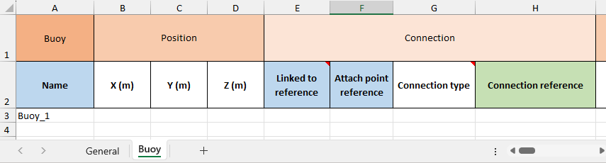
If no buoy data are filled in the Buoy sheet, the buoy has the default data assigned by DeepLines.
Defining objects without name
To define a default HAWT, it is not necessary to define the HAWT component sheets (like HAWT Blade, HAWT Tower, etc.), only a name defined in the Name column of the HAWT sheet is enough to define a HAWT by default:
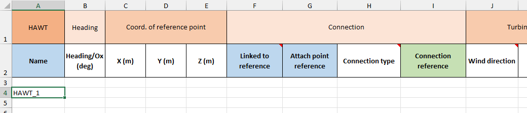
And the model tree in DeepLines GUI has the following content:
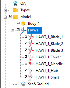
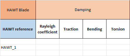
The HAWT component sheets do not have a Name column, because HAWT components have names imposed by DeepLines based on the HAWT name. For example, to define blades data, you have to only specify the name of HAWT to which the blade belongs in the HAWT reference column:
Defining objects referencing multiple names
Some objects cannot be uniquely defined by their name. It is the case, for example, of:
-
A line segment. In the Segment sheet, the same name "seg_1" can be used for two segments belonging to two different lines, so to uniquely identify a segment, it is necessary to specify the reference of the line section to which the segment belongs:
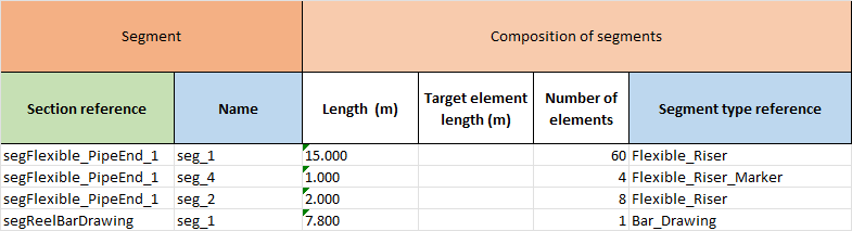
Note that a section name is relevant only for the Excel format and has no equivalent in DeepLines model in which line sections are unnamed. The sections names are to be defined in the Section sheet, and are referenced in the Segment sheet.
-
An environment set component. In DeepLines, an environment set component, like a current, can have the same name in two different environment sets, so to uniquely identify a component, it is necessary to specify the reference of the environment set to which the component belongs:
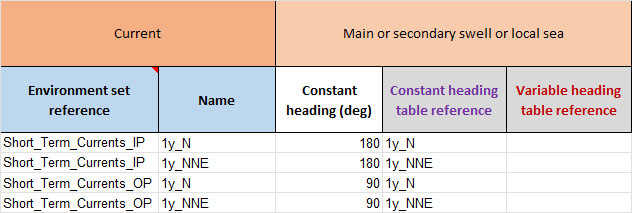
In the Current, Swell, Wind, Offset, LF motion, Floater motion, Prescribed, Turbine and UDK sheets, an environment component must reference an environment set to be defined. Note that a current, a swell or a wind can be defined without the reference of an environment set if it is a standalone object not belonging to an environment set. And a swell can reference a wave set in place of an environment set.
Defining several kinds of objects in the same sheet
Some sheets group multiple kinds of objects in the same sheet. For example, the Structure properties sheet allows the user to define steel materials, local sections and stiffeners:

The Connection sheet, used to define properties of connection between objects, allows to define properties of user-defined, flexjoint or spring connection.
The Joint sheet contains the definition of the joints and the definitions of the subjoints properties, stiffnesses and SCF.
Defining object and its type in the same sheet
A few rare sheets include the definition of an object as well as the type, it is the case of the Ballast sheet, for example.
Defining an object across multiple rows
Generally, an object is defined by a single row with its name and data values. However, some objects need to be defined on multiple lines. In this case, the same object name must appear on as many lines as necessary.
For example, the Fairlead sheet allows to define "fairlead" objects that have no equivalent in the DeepLines model. Each of these "fairlead" objects is a concept specific to the Excel format, allowing to group all DeepLines fairleads under a single name so that this set of fairleads can be referenced by an object.
The Mesh, Rigidification and Analysis set sheets are another examples of sheets where a same object can be defined across multiple rows.
Cross-references
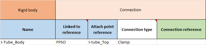
If the definition of an object requires referring to another object (for example to define a connection between objects) the referenced object must be specified in a column whose name ends with reference and this referenced object must have been named and defined in the column Name of another sheet.
For example, in the Rigid body sheet, the "I-Tube_Body" object is linked to the "FPSO" object as indicated in the Linked to reference column:
The "FPSO" object is defined in the Floater sheet whose name is registered in the Name column:
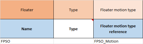
In the same way, the Floater motion type reference of the "FPSO" floater is "FPSO_Motion" which is defined in the Floater motion type sheet:

Filling data values
Generally, the data for an object named in the Name column should be entered after the name on the same line if those values are scalars. The column name on the second line provides the data label.
The data can also be a table of values. In this case, the cell contains a reference to a table, which is defined in additional columns, most often within the same worksheet. The table definition consists of specifying the table name in its first column, with as many rows as there are values defining a component of the table. The table contains as many columns as there are components.
The same table can be referenced by several objects, and for some objects, a reference to a table can point to different tables depending on the object in question.
According to the same principle as cross-references between objects described in the previous section, a table is referenced during the definition of the object in a column whose name ends with table reference, and it is defined and named in the same sheet as the object in a column ending by table name.
For example, in the Calculation parameters sheet, the calculation parameters "CalcParam" references a "Contact" table in the Contacts table reference column. The content of the "Contact" table is defined by as many rows as the table name appears in the Contacts table name column.

Warning
The notion of a table of values mentioned here is specific to the definition of the model with Excel (the name of such a table does not appear in the DSK model) and should not be confused with the notion of a variation or environment table which is an integral part of the DSK model (their names appear in the model tree under the Tables folder). In the Excel model, the variation and environment tables are to be defined in the Table sheet and are to be referenced in the columns with a name like:
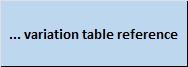
on a blue background cell (color code indicating that the table is defined in another sheet, see below). Variation or Env table in Excel format is described in the Tables section.
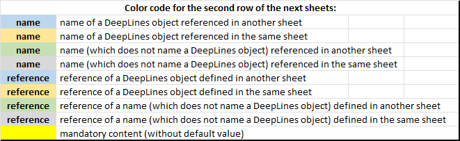
Colors are used to identify the columns which name and reference objects, as indicated in the following table which is recalled in the DeepLines sheet:
Options list
Some columns must be populated with a predefined value.
In that case, the column name cell has a note:
see the red triangle at the top right of the column name cell in figure below.
By hovering the mouse over the red triangle, the list of possible values is displayed.
When a (default) indication follows one of the predefined values, it is this predefined value which will be taken into account if a cell is left empty.
Note that the predefined value to enter is not case-sensitive.
Instead of typing the full option name it is possible to enter the number of the option in the list.
For example, in the extract from the Excel sheet concerning a rigid body below, the two rigid bodies "Braces" and "column" are connected with the floater "Floater_1" with a Clamp connection: for the first one, the connection type Clamp is indicated explicitly and for the second one, the number 2 is specified because the clamp connection is second in the list of options.

Specific sheets format
Sheet "DeepLines"
The DeepLines sheet is mandatory and is used to determine whether the data in the Excel file is used to define a DeepLines model. This sheet must have a predefined cell Dsk File on the first column of the sheet. The content of the cell immediately to the right is read and used to determine the name of the DSK file to create, see Importing a DSK model from an Excel file section below. Actually, only these two cells are interpreted in the DeepLines sheet.
If the Excel file contains only the DeepLines sheet, an empty model is created which corresponds to that created when you do Files → New from the GUI toolbar.
The old name General can be used in place of DeepLines.
Sheet "Table"
The Table sheet is used to define Variation or Env tables:
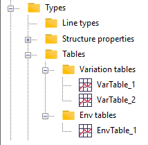
Apart from the two column names Name and Type, other columns have no name in the second row, unlike the other sheets. The columns names of a table are defined for each table on its first row: they will be the titles of the GUI table columns.
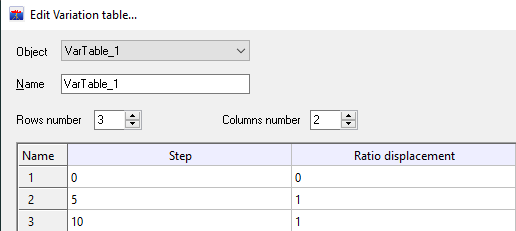
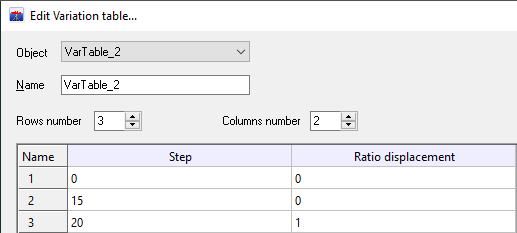
For example, if the Table sheet has the following content:
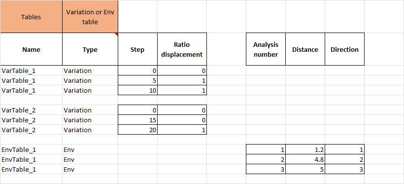
The "Step" and "Ratio displacement" column names are defined by the user and they appear as the titles of the variation tables columns in the GUI.
| |
| |
|
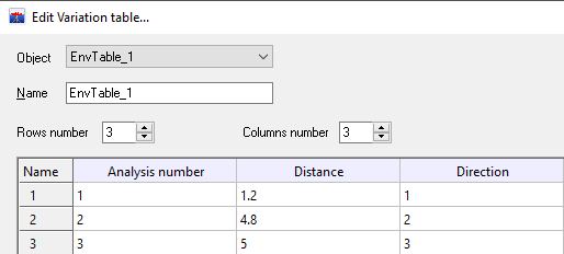
And the Env table appears in the GUI as shown in the following screenshot:
Sheet "Mesh"
In the current version, when reading an Excel file, a mesh for a floater, rigid body or sea & ground is read from the mesh file if it exists, otherwise it must be defined in the Mesh sheet. But only mesh with triangles and quadrangles can be defined in the Mesh sheet.
A mesh for a floater, rigid body or sea & ground is written in the Mesh sheet only if the mesh file does not exist.
Numbered columns in "Environment set" and "Joint" sheets
The combination matrix of an environment set depends on the number of floaters and prescribed motions or loadings.
So, in the Environment set sheet, the user can add as many columns for Offset reference, LF motion reference and Floater motion reference as there are floaters.
To add a column, the user must follow the column name with an integer. For example, with 2 floaters, the columns names will be of the form:

There are two ways to number:
- Either the numbering starts at 1 up to the number of floaters (see the Offset reference numbering in the previous example),
- Either the first column has no number and the following ones start at 1 (see the Floater motion reference numbering as example).
The numbers must follow each other.
The same way of numbering the columns applies if the number of prescribed motions or loadings is greater than 1.
To define the joints, you must specify the chords and braces. Each chord or brace is defined by a line and segment.
In the Joint sheet, the user must enter as many columns of lines and segments for chords as the maximum number of chords used to define the joints.
Each line or segment column name has a name that ends with chord followed by an integer.
The same goes for braces.
In the example below, you need 2 chords and 3 braces to define the 5 joints:

Symmetric matrix in "Loading" and "Floater motion type" sheets
For the Symmetric matrix table in the Loading sheet, only the upper part of the matrix should be filled:
if there are values in the gray area, an error will be displayed in the LOG_History.txt file.
The 6 lines of the matrix must be filled in otherwise an error will occur.
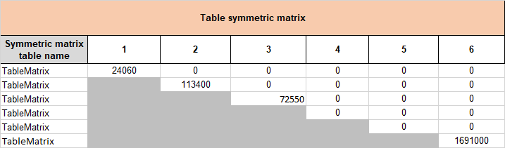
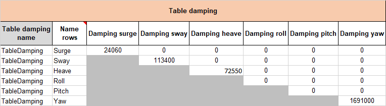
Likewise, for the Table damping in the Floater motion type sheet,
only the upper part of the matrix should be filled: if there are values in the gray area, an error will be displayed in the LOG_History.txt file.
In the column Name rows, the only possible values are: Surge, Sway, Heave, Roll, Pitch, Yaw.
Importing or exporting an Excel file
Importing a DSK model from an Excel file
Once the model data are defined in the Excel file, a DSK file can be created using one of the following two ways:
-
In batch mode using the option
-createDskfollowing by the Excel file:DeepLinesGUI.exe -createDsk FILE.xlsxThis command creates the DSK file from the data in the Excel file without opening the GUI.
The name of the DSK file depends on the content of the cell immediately to the right to the Dsk File cell of the DeepLines sheet:
- If this content is empty, the name of DSK file will have the same base name as the Excel file but with the extension
.dsk. - If the content has been filled, the DSK file will take this entered name. (The
.dskextension is added only if the entered name does not contain this extension).
- If this content is empty, the name of DSK file will have the same base name as the Excel file but with the extension
-
Interactively:
-
By doing a drag and drop of the Excel file into the main GUI window.
-
By launching the executable with the name of the Excel file as argument:
DeepLinesGUI.exe FILE.xlsx -
By selecting the Import from Excel item of the File menu which opens a dialog box:
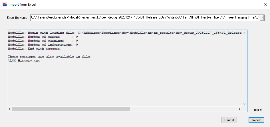
The model with the data read from the Excel file will be loaded in the GUI.
Warning
The DSK file will have the same base name as the Excel file but with the extension
.dsk(the Dsk File field of the DeepLines sheet is not interpreted in that case): if a DSK file with the same name is present in the directory, it will be overwritten. -
Exporting a DSK model to an Excel file
An Excel file containing the data of a DSK model can be created either in batch mode or interactively.
-
In batch mode using the option
-createExcelfollowing by the DSK file:DeepLinesGUI.exe -createExcel FILE.dskThis command creates the Excel file from the DSK file without having to open the GUI.
By default, the name of the Excel file will have the same base name as the DSK file but with the extension
.xlsx. The Excel file will not be created if a file with the same name already exists, unless the-ow(for overwrite) option has been specified. -
Interactively, by selecting the Export to Excel item of the File menu which opens a dialog box:
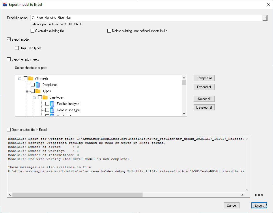
The dialog box allows you to specify empty Excel sheets that will be written to the file in addition to the sheets used for translating the model data. To do this, select the sheets listed in the tree view.
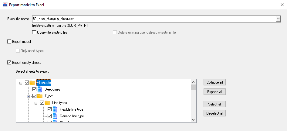
To create a file empty of data but containing all available Excel sheets, uncheck the box Export model, check box Export empty sheets and select all the cells in the tree by simply checking the first one All sheets:
Importing or exporting specific sheets
The Joint, Structure properties or Code check study sheets can be imported or exported independently of other sheets.
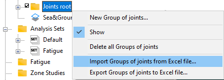
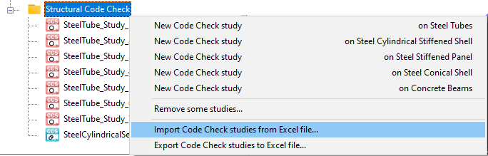
As described next, the Joints root, Structure properties and Structural Code Check folders in the tree view, have two items in their contextual menus: Import from Excel file... and Export to Excel file....
The Excel file to import must have the concerned sheet and only this sheet is read. If an object defined in the Excel sheet is already present in the DSK model, its data are replaced with those contained in the sheet.
For exporting data in Excel format, only the concerned sheet is written in the Excel file. If an object defined in the DSK model is already present in the Excel sheet, its data are replaced with those contained in the DSK model.
Joint
Contextual menu of the Joints root folder (see Defining joints manually section):
Structure properties
Contextual menu of the Structure properties folder (see Structure properties section):

Code check study
Contextual menu of the Structural Code Check folder (see Code check study section):
In batch mode, for the code check computation from the DSC file (see Running a code check study section), it is possible to load an Excel file with option -loadExcelFile:
DeepLinesGUI.exe -console -loadExcelFile FILE.xlsx MODEL.dsc
In that case, before the code check computation, the Excel file is loading and can overwrite code check data contained in the DSC model: a code check computation can be executed with a new set of data without opening the GUI. Only the three sheets (Joint, Structure properties or Code check study) are decoded in the Excel file.
Output messages
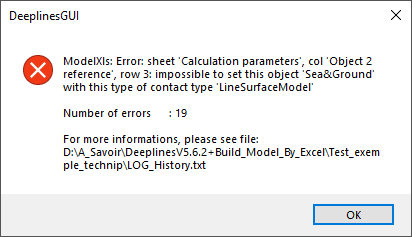
If problems are detected when reading data from the Excel file or writing model data in the Excel file, messages are produced in the LOG_History.txt file. All messages concerning the translation start with the "ModelXls:" string.
There are 3 levels of messages:
- Error:
At least one data item could not be interpreted and the DeepLines model is not built (and the DSK file is not created).
TheLOG_History.txtfile ends with "End with error". - Warning:
At least one data item is missing but the DeepLines model can be created (for example, if an expected data item is a file name and this file is not found, a warning is issued).
TheLOG_History.txtfile ends with "End with warning (the model is not complete)". - Information:
A problem has been detected but it is not possible to know if it is an error (for example, a column name is not recognized, but it is not known if this name was misspelled or if it is a column that was added by the user).
TheLOG_History.txtfile ends with "End with success".
For each type of output there is a counter that allows you to see the number of messages because only the first 20 messages (of each level of output) are written in the LOG_History.txt file for the sake of readability.
In interactive mode, a window displays the first message of the highest message level (but all the messages are still logged in the LOG_History.txt file):
If the import or export dialog box is used to transfer data, the output messages also appear directly in the area of the dialog box designed to receive them.
