Home > Model Components > Lines > Bent Lines > Bent Line Shape
Bent Line Shape
This sheet allows you to define the geometry of the Bent Line. This tab is composed of 3 main areas: the Reference Axis System , the Construction Segment and the Bend Definition.
The shape of any Bent Line is defined through the number, length and coordinates of its straight line segments, and the radius of the bent segments that link two consecutive straight segments.
Reference axis system
This defines the direction about which the Bent Line will rotate should you specify an angle of rotation. This allows to set the orientation of the bent Line towards any direction you like.
Construction (straight) segments
The construction segments represent the straight segments. that are used to define the shape of the Bent Line. Initially, there is one construction segment. The Add button allows to define a new construction segment. The new segment will be added at the end of the list. New segments are assigned a name automatically, but this can be edited directly in the table. Alternatively, the field Number of Construction Segments can be used to set the required number of construction segment in one quick step.
After creating the number of construction segments you require, it is necessary to set their characteristic lengths \(\Delta X\), \(\Delta Y\) and \(\Delta Z\).
Bent segments
Any bend is defined by specifying the two adjacent construction segments the bend connects to, and the bending radius.
The length of the bend and the bend angle are automatically calculated.
Initially there is no bend defined. The Add button allows to create new bend sections. The new bend will be added at the end of the list. New bends are assigned a name automatically, but this can be edited directly in the table. Alternatively, the field Number of Bends can be used to set the required number of bend in one quick step.
Generate Segments
When the construction segments and bends are defined, clicking the Generate Segments button updates the composition of Segments table in the Structure panel.
Example:
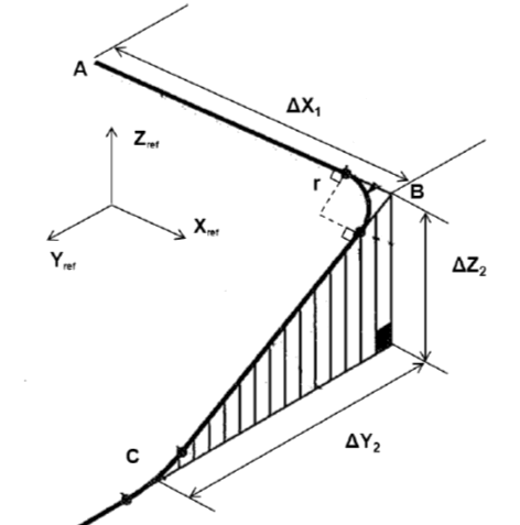
_To create the linepipe presented in the following figure, the shape must be defined as follow:_
- $1^{rst}$ construction segment = $\{\Delta X_1; 0 ; 0\}$
- $2^{nd}$ construction segment = $\{0 ; \Delta Y_2 ; \Delta Z_2\}$
- Bend radius = $r$

